The high availability and reliability of power supplies in industrial and purpose-built environments is a critical factor for cost efficiency and productivity. Unexpected interruptions, malfunctions and EMC problems cost time and money. As part of preventive maintenance, it is therefore important to monitor power supplies permanently. Modern residual current monitoring systems (RCMS) detect serious insulation faults at an early stage and enable the operator of a technical system to locate and rectify the fault quickly before a sudden malfunction or shutdown of the entire operation occurs.
In addition, the potential for savings are possible with periodic verification according to the the German accident prevention regulation (DGUV regulation) 3 and the industrial safety regulation (BetrSichV).
This article is intended to show practical solutions for innovative residual current monitoring in order to guarantee operational reliability through preventive maintenance for modern electrical installations in highly sensitive areas. An investment that pays off.
Within fixed electrical systems and equipment, residual current monitoring systems (RCMS) offer an optimum possibility for the permanent assessment of insulation degradation. The measured residual currents can be clearly assigned to the respective circuits and current using equipment. An installation-related safety/hazard assessment is possible.
The advantages of these measurement methods lie above all in prevention, i.e. these measurements can be carried out continuously and provide the necessary measured values for the safety/hazard assessment of the electrical system at an early stage. In terms of electrical safety, in particular that of electrical equipment which must be continuously available, or systems where it is difficult to measure insulation resistance for technical reasons, this measurement method offers many advantages for practical operation.
However, the application of these measurement methods does not exempt the user from the obligation of carrying out periodic verification of the electrical installation and equipment in accordance with DGUV Regulation 3, e.g. by inspection, testing the continuity of the protective and equipotential bonding conductors and the effectiveness of the switching/disconnection conditions.
The now valid Industrial Safety Ordinance § 10 requires a similar test to be carried out. According to the risk assessment in accordance with § 3 of the BetrSichV, the type, scope and intervals of the necessary tests must be determined for current using equipment in particular. Defects and damage must be detected in good time by these tests. How this inspection is to be carried out is not specified in detail. The person responsible must define the necessary measures and inspection intervals for the residual current monitoring devices used in practice.
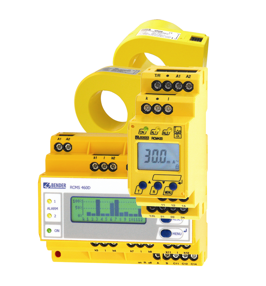
The job of a Residual Current monitoring device (RCM) (as shown in Fig. 1) is to monitor an electrical installation or circuit for the occurrence of a residual current and to indicate by an alarm if this exceeds a specified value. [DIN EN 62020 (VDE 0663):2005-11].
A fundamental law of electrical engineering, Kirchhoff's first theorem, states that the geometric sum of the currents in an electric circuit equals zero. As shown in Figure 2, in a fault-free network, I1 is the same as I2.
According to Kirchhoff's theorem, if a fault current IΔ is generated due to an insulation fault between an exposed-conductive-part body or earth, this results in a fault current:
I∆ =I1 – I2
With the RCMS460 system, which measures 12 channels of True RMS values and is sensitive to universal currents, residual currents of 0 ...2000 Hz and 6 mA to 20 A can be measured during operation and evaluated within 180 ms.
The system, which is equipped with a display, signals whether preset response values or response times have been reached or already exceeded. An integrated history memory and data logger function stores up to 300 messages with exact fault times. Information is exchanged between the individual evaluation devices and a gateway via an RS-485 interface. Thus, a complete building or a complete supply section can be permanently monitored from a central location, e.g. a control cabinet or a control room.
By documenting the installation behaviour over time, it is possible, within the framework of permanent residual current monitoring, to define adapted test intervals in accordance with DGUV Regulation 3 and thus to fulfil the protection objective of the BetrSichV "Definition of hazard-related test intervals".
The protection targets of the BetrSichV and DGUV Regulation 3 with regard to the periodic tests to be carried out are always met if it is ensured that the electrical equipment is free of defects. In addition to the fixed test interval, fixed electrical installations can also be subject to "continuous monitoring". For mobile electrical equipment, the DGUV Regulation 3 implementation directive "Electrical Installations and Equipment" permits, in addition to the strict reference to the assigned test intervals, an extension to the intervals if a fault rate of less than 2 % is determined. Solutions are conceivable if it is ensured that only proper equipment in full working order is made available to the employee.
Using the differential current measurement methods presented here, it is possible for the electrician (or qualified person according to the BetrSichV) to determine clear and meaningful test intervals and to define them for specific applications. This definition can include both a reduction and extension of the test intervals. Depending on the "degree of use" of the equipment, it is possible to carry out a periodic test that is adapted to safety and economic aspects (determination of time intervals).
Switching off, even for short periods, are a thing of the past thanks to the targeted use of residual current monitoring systems (RCMS). The availability of an electrical system is increased and the cost of the periodic testing of electrical systems and equipment is minimized.
The main advantages are summarized below:
Optimized maintenance
Higher operational/plant safety
Higher economic efficiency
Higher fire safety
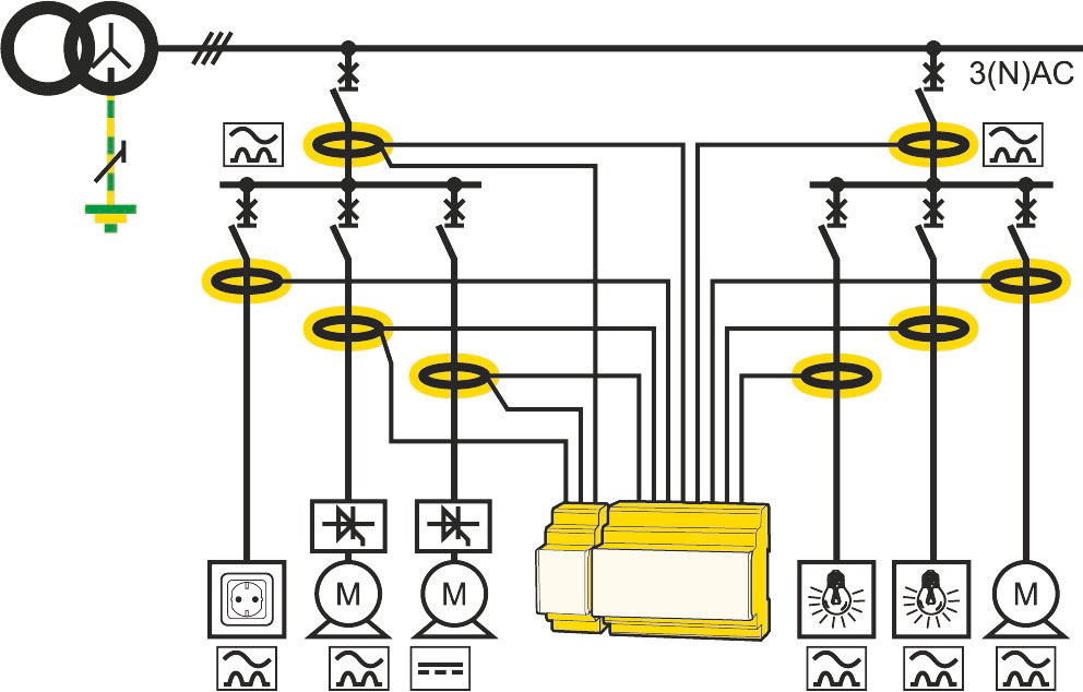
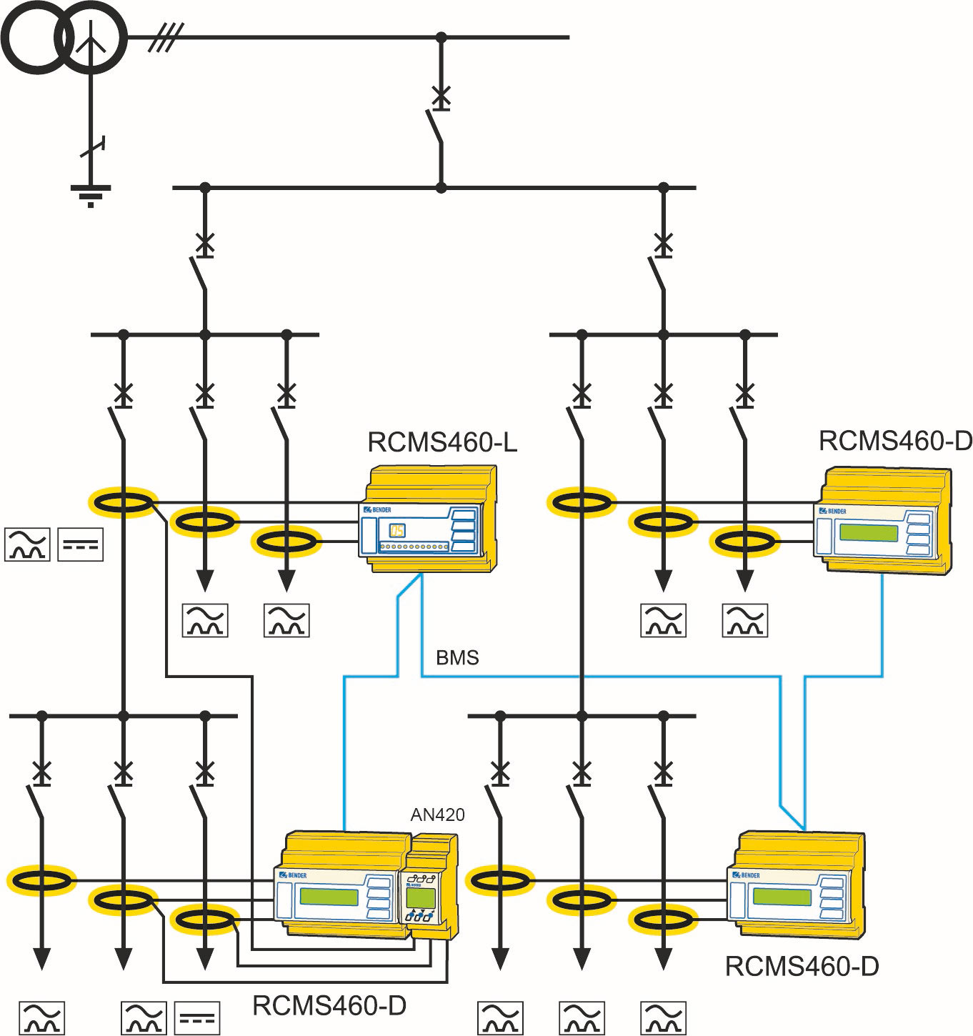
The basic structure (Fig. 4) shows the circuit monitoring of the power supply with up to 12 outputs (circuits). The preferred installation location of the required measuring current transformers for determining the fault current is also shown and simultaneously serves for fault location detection (circuit assignment).
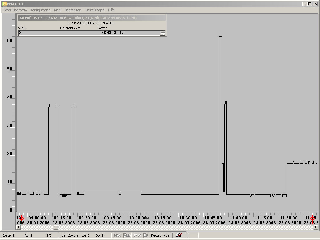
Individual measured values from the residual current monitoring systems can be easily viewed from the electrician's workplace. Changes or fault currents that occur in the power supply to be monitored are shown graphically and documented (Fig. 7). Thus, the fault location/final circuit can also be determined beyond any doubt.
The following section compares conventional DC insulation resistance measurement with the monitoring of the system with residual current monitoring systems in conjunction with test personnel (Table 1).
| Disadvantages of an insulation measurement with DC measuring voltage. | Advantages of RCM measurements |
|---|---|
| Ageing and previous damage of varistors by insulation measurement with high DC measuring voltages. | RCMs are passive monitoring devices - this source of error is excluded. |
| Test currents which are too high or which are applied for too long can damage (i.e. burn) protective relays. | RCMs are passive monitoring devices - this source of error is excluded. |
| Loads that have not been disconnected from the mains during the insulation measurement can be damaged. | RCMs are passive monitoring devices - this source of error is excluded. |
| UPS supported system components cannot be measured - no switch-off possible. | RCMs are passive monitoring devices - this source of error is excluded. |
| In extensive networks with large conductor cross-sections and meshed networks, the time required for coordination, insulation testing and evaluation is often not justifiable for economic reasons. | RCMs can perform the task of detecting insulation degradation at a cost that is both technically and economically acceptable. |
| Periodic verification is very often only random checks. They are not representative and can display different values due to climatic conditions, for example. | RCMs monitor online. A trend analysis and a statement about future failures can be made when measured values are logged and evaluated. Defects that pose a danger to persons, livestock and property must be rectified immediately. |
| Electronic equipment can be damaged by the test voltage if the neutral conductor is not disconnected or if some form of connection due to insulation faults, for example, is present. In these cases, there is a risk that the test voltage of the insulation measuring device may occur at the input terminals of the equipment. | Disconnection of the neutral conductor is not necessary. Terminals necessary to disconnect the neutral are therefore not required.. |
| Internal shutdown problems; not all system components are checked. | No switch off is necessary. |
| Operating processes and downtime costs are influenced due to shutdowns. | No costs incurred due to downtime. |
| Connecting the neutral conductor disconnecting terminal as a hazard point for interruption, or forgetting the connection after measurement. | The disconnecting terminal for the neutral conductor does not have to be used. |
| N conductor disconnecting terminals are known to be a weak point in the event of high harmonic currents. An interruption causes a voltage increase. | The disconnecting terminal for the neutral conductor does not have to be used. |
| In the de-energized state, measurements can only be made up to the protective separator. | RCMs measure the complete installation, including powered fixed and mobile equipment. |
| If the insulation resistances of several circuits are tested together, coupling between different circuits may remain undetected. Possible consequences are feedback voltages and the function of the RCD may be restricted. | RCMs detect such couplings when each circuit is individually monitored. |
| No meaningful measurement results in the presence of surge arresters. |
| Disadvantages of an insulation measurement with DC measuring voltage. | Advantages of RCM measurements |
|---|---|
| High staff retention and considerable cost factor. | |
| Qualified personnel with knowledge of the test equipment are required. They must be familiar with the relevant safety requirements, regulations, operating instructions and the hazards associated with the work. A sufficient number of persons working on electrical systems must be trained to be able to provide first aid. Correct documentation is necessary but in many cases not available. | No expert and knowledgeable personnel are required for monitoring. An electrician is only required when the fault current exceeds the limit value. |
| Possible hazards and stresses the tester may encounter include: 1. inadequate preparation, risky improvisation, working under time pressure 2. working with safety devices that have been switched off or dismantled 3. working under difficult conditions in the surroundings 4. working on conductors 5. working when the system is energized or in the vicinity of live conductors. | No dangers. |
| Further distinctive features of RCM measurements | Advantages of insulation measurement with DC measuring voltage |
|---|---|
| An insulation fault between active conductors is not detected. Insulation faults between N and PE can be measured if loads are connected and switched on. | Can be measured. |
| RCMs can only be used in TN-S and not in TN-C systems. | Response value from approx. 5 mA: Insulation faults smaller than 40 kΩ between phase and earth can be measured. |
| Detection by the response value - no high-impedance insulation faults according to DIN EN 5110-1 (VDE 0105-1):2014-02. | The insulation test detects symmetrical and asymmetrical ohmic insulation faults. Capacitive fault currents are not fire-hazardous because they are evenly distributed over the length of the cable. |
| Detects only unsymmetrical capacitive and ohmic insulation faults. | Bei der Isolationsprüfung werden symmetrische und unsymmetrische ohmsche Isolationsfehler erfasst. Kapazitive Fehlerströme sind brand-ungefährlich, da sie sich gleichmäßig auf die Leitungslänge aufteilen. |
| There are no standardized response values yet. The response values can vary greatly depending on the mains leakage capacitance and the system. The selection of the correct response value must be carried out by a qualified electrician. | Minimum values of the Insulation resistance are specified in DIN VDE 0100-600 (VDE 0100-600): 2017-06 , subclause 6.4.3.3, Table 6.1. |
| Conditionally applicable in system parts where no protective conductor is distributed. For a reliable assessment of the insulation resistance, the PE should always be distributed. | |
| In IT systems, the residual current cannot be assigned to an insulation fault downstream of the measuring current transformer. | Can be used in all types of networks. |
Within fixed electrical systems and equipment, residual current monitoring systems offer an ideal opportunity for assessing insulation degradation. The measured residual currents can be clearly assigned to the respective circuits and thus a plant-related safety assessment is possible. Therefore, the measuring method of the residual current monitoring devices (RCMs) to be used and the installation of the measuring current transformers must be selected to meet the system requirements. Within the framework of continuous monitoring, such monitoring equipment can ensure the required "continuous" metrological testing.
Similarly, in the case of circuits that are monitored by residual current monitoring systems, the connection of faulty hand-held electrical equipment is measured, visualised and, if necessary, the circuit is switched off. This assumes that the permissible threshold values of the differential current are specified by a qualified electrician for the specific system. The chronological documentation and graphic representation of the system behaviour, e.g. a reduction of or increase in the differential currents, make it possible to define adapted test periods for the electrical equipment to be connected.
If it is determined within the organisation which equipment is to be used for operational reasons, the test intervals can be corrected on the basis of the measurement results. Practical experience to date has clearly shown that this measurement method makes it possible to assign individual periodic tests in a tailored manner and therefore meet the protection objective of the BetrSichV "Festlegung gefährdungsbezogener Prüffristen" (Specification of hazard-related test intervals)
| Name | Category | Size | Language | Timestamp | D-/B-Number |
|---|---|---|---|---|---|
| Product Overview - Residual Current Monitoring | Product Overviews | 4.2 MB | EN | 2026/02/1111.02.2026 |
Products

Four-channel DC, AC and pulse current sensitive residual current monitors for earthed AC, AC/DC and DC systems

Multichannel AC, pulsed DC and AC/DC sensitive residual current monitor
Four-channel DC, AC and pulse current sensitive residual current monitors for earthed AC, AC/DC and DC systems
Multichannel AC, pulsed DC and AC/DC sensitive residual current monitor